What are these things?

US military AN/TVS-3 battlefield illuminators, built between 1968-1971. Made by Strong Lighting (remnants of this company still exist) and Varo. They cost the military $23,000 each in 1968.

Project Flashlight reanimated the old lights and added new servo systems controlled by tablets or phones.
What were they used for?
They were intended to illuminate tank battles. There is an optional infrared filter that blocks all visible light, so soldiers could see with infrared night vision goggles – which was secret US technology in the 1960s.
The intended tank battles never happened.
The Army tried these out in Viet Nam, pointed at the clouds to provide starlight night vision enough light to operate on moonless nights.
There were Army searchlight battalions. The UK even had a few.
Were these used for anti-aircraft?
These are not anti-aircraft searchlights, during WWII radar took over for searchlights.
The big-anti-aircraft searchlights were 60” diameter lit with a carbon-arc, built in the 1930s. Those also included analog computers to track aircraft and servo control guns. Amazing technology for the time.
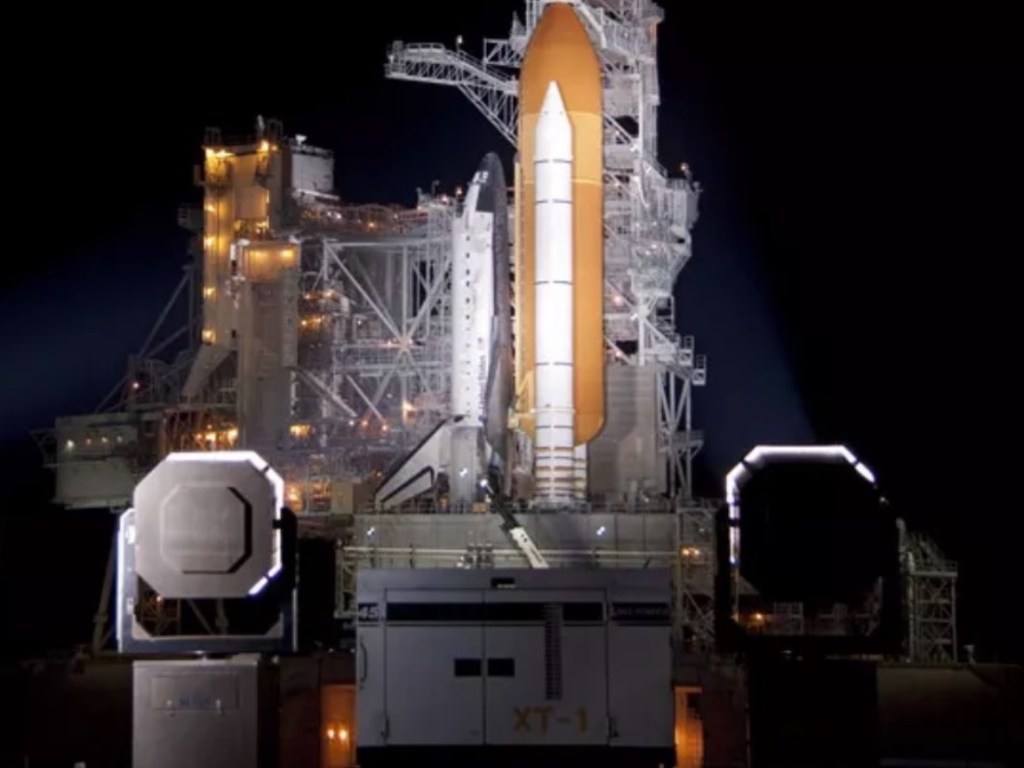
NASA, Apollo and Space Shuttle
In the 1960s NASA needed to light up night operations and launches.

So NASA (USAF) obtained about 150 AN/TVS-3s and used them to light up launch pads, from Apollo in the 1960s through the Space Shuttle in 2011.
NASA engineers kept these in continuous operation and made a number of modifications to improve reliability and maintainability.

After the end of the Shuttle program, NASA decided they had no need for AN/TVS-3s – they didn’t need to light up big rockets and the AN/TVS-3s needed 400 Hz power, were unique and hard to maintain. So USAF (the actual owner of the bases) dispositioned them. Someone in USAF thought the lights had potential military use, so most were destroyed, except for about 20.
Oops, NASA/USAF still needed lights for night operations, so they had the SEL-10 custom made by Ballantyne Lighting. Then they didn’t, so we have 6 of these too.
Project History
Some of the history and technical details are on the Candlepower Forums AN/TVS-3 Project Page.
Where did you get them?
Neal saw an AN/VSS-1 tank searchlight (the “Death Ray”) at Burning Man in 2011 used for the emergency services beacon, so had to have one too. He found one on eBay and made the mistake of asking the seller what else he had that was interesting, and (with encouragement from Brett Peabody who originally dived into the TVS-3 to build his searchlight firetruck and split the cost) ended up with 10 AN/TVS-3 searchlights, 3 generators and a ton of spare parts, delivered to Building 180 on Treasure Island in San Francisco. Those had been sitting in a field for 25 years, and were unfortunately basically scrap.
But that was the start of Project Flashlight.
After giving up on those first 10 units, Neal located 8 more ex-NASA lights in good condition. Some had escaped being destroyed by being transferred to Customs and Border Patrol with the intent to illuminate the border. CBP couldn’t figure out how to turn them on, so they surplused them out, and after a few stops those units made their way to Treasure Island. Once we flushed out the automotive radiator coolant they lit up!
Why?
For art! Beams in the sky, creating unexpected and dynamic spaces and shapes.
And just interactive fun converting diesel fuel into photons.
Who else?
We know of 3 other “searchlight enthusiasts” in the US who maintain working AN/TVS-3s.
Technical Details
Lumens? Candlepower?
The military specification is 1.2 billion candlepower at 20kW, 800 million candlepower at 15kW, 600 million candlepower at 10kW. Our mirrors are pitted from 45 years of being outside in the salt air at Cape Canaveral, so we’re losing a bit.
Approximately 2 million lumens at 20kW (≈100 lumens/Watt).
What is the lamp?
The lamp is a 20kW liquid-cooled xenon short-arc. It’s about 27” long. ¼” thick quartz glass. These same lamps (with different fittings) are used in IMAX projectors up to 32kW. These are not carbon arcs.
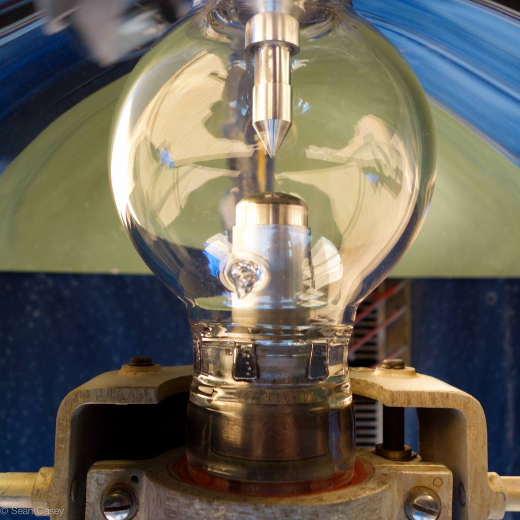
Replacement lamps are available for $8000 each, rated at 400hrs or 400 starts at 20kW.
Volts? Amps?
At 20kW the nominal is 43VDC (full-wave-rectified 400Hz 3-phase so 1200Hz bumpy DC) at 465A.
The start pulse to initiate the arc is 45kV generated with a spark-gap tank circuit. Boost voltage is 160VDC, to grow the arc to operating range, it then pulls current from the main supply.
Spectrum
The pure xenon short-arc is a very full spectrum, from infrared (51% output) all the way to UV-C (blocked by the glass). So with 60% overall efficiency, that beautiful white beam that you see is only about 20% of the power input.

Liquid cooled?
Considering the lamps are about 60% efficient they dissipate up to 8kW of heat.
The anode (round end) is a hollow tungsten cup, with coolant pumped into a tube aimed at the back of it, then circulated to the cathode (pointy bit). The 2hp pump circulates 6 gallons/minute at 150psi through a ¼” tube.
The liquid cooling hoses are bronze and also carry current to the lamp.
EMI
The lights came from NASA with fancy chicken wire under the lenses. It turns out that the 400Hz 3-phase rectified-but-unfiltered DC throws a lot of EMI at harmonics of 1200Hz, nicely focused with the beam. When NASA first lit up Apollo at night the EMI crashed the computers. So chicken wire Faraday cages were added.
We have brought down drones with the lights.
400 Hz
These units run on 400Hz AC. Aircraft, ship, and some military AC power is 400Hz instead of the 60Hz US standard or 50Hz most other places.
400Hz motors and transformers are 7x more efficient than 60Hz, much smaller and lighter for the same output.
The cooling pump and fan are standard military aircraft parts repurposed for this use. Rectified 400Hz AC is used to feed the lamp directly.
Reflectors
30” diameter parabolic reflectors, made of electroformed nickel and plated with rhodium.
Coolant
The coolant is a dielectric water/ethylene glycol antifreeze – it needs to be dielectric (non-conductive) to not short out the 45kV start pulse.
Originally a Dow Chemical Norkool formulation they don’t make anymore. They offered to brew up a batch, but the minimum order was a tank-car (6,000 gallons) so we passed and came up with our own custom coolant.
Pure water and pure ethylene glycol are dielectric, the challenge is the pH buffer and corrosion inhibitors also need to be dielectric. We use triethanolamine for pH of 7.75, benzotriazole 100ppm and sodium molybdate 100ppm. New coolant measures about 18µS. (Unfortunately we can’t find a dielectric inhibitor for aluminum – if you know of one send an email!)
Why go through all that trouble and not use some commercial dielectric coolant? Cost (less than $10/gallon) and pH and corrosion inhibitors for our mix of metals.
What makes all that noise?
The generators are military “tactical quiet” and actually fairly quiet.
Each light has a water pump (the whine) and a 5” aircraft-style fan spinning at 11,000rpm (the howl) pulling cooling air through the radiator at the bottom, the rectifiers, around the lamp and out the top.
How do the servos work?
Android tablet (OSC client) -> WiFi -> Raspberry Pi (OSC server, space transformation, servo interface) -> Roboteq motor controllers (PID) -> 24V DC motors.
The AN/TVS-3 was designed as a battlefield illuminator: point it at a battlefield, turn it on, run away ‘cause you’re now a target, if it’s not destroyed – great. A completely manual operation.
So a big part of the project was adding automation. Without spending insane amounts of money. Playa-proof.
So we fit to the existing design.
Elevation servo is a custom sprocket (waterjet) fit over an existing part, driven by a 250W Chinese Razor Scooter motor, with direct feedback potentiometer inside the arm. We have a software limit to not go flat and blind people.
Azimuth servo is custom internal gear (waterjet, CAD by Andy Lee) driven by a 250W Chinese wheelchair motor, with 10-turn feedback pot driven by a gear with calculated ratio. The first version of azimuth drive used a toothed belt, which required less engineering but only rotated 180° and failed frequently.

Each set of 24VDC motors are driven by a Roboteq LDC2230 2-channel 60A controller that implements PID (Proportional Integral Differential) using potentiometers for absolute position feedback.
The lights don’t have slip rings, ultra-flexible cables (36AWG stranding with asbestos insulation) coil in the base, so rotation is limited to 540° (once around + 90° in each direction – limited by a toggle lock).
It’s all powered from the generator 24V starter batteries and alternator.
What is the software?
Rob Gaunt wrote the server software in Python running on a Raspberry Pi. It provides an OSC (Open Sound Control) server, translating OSC inputs and transforming sky or GPS coordinates into servo position commands.
What are the apps?
The tablet and phone run the TouchOSC app with custom layouts for direct control and sky-mapped grid positions.
Rob Gaunt also created an Android Spirograph application in Processing that continuously moves 4 lights through arcs.
Light sabers?
Light sabers – lights following movement are neat. Rob implemented this with PSMove controllers, but they don’t maintain position and drift to flat after about 10 seconds, so pretty useless. (At the time, there was no good open source Wiimote library.)
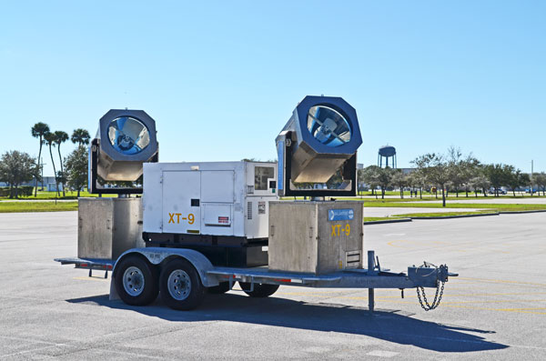
What are the generators?
The generators are military MEP-816A 60kW 400Hz “Tactical Quiet”, and were actually used at Cape Canaveral to power these lights (note rusted areas from sitting out in salt air for years). The engine is a 6 cylinder turbo-diesel. They put out 3-phase 120/208VAC at 208A per phase. Military rated 60kW means they will put out 25% more (72kW) for extended periods.
Trailers?
The trailers are custom made by Frank Domingo at Modesto Trailer Repair (who also runs concrete pumps and tuna fishing charters). The wheels are in non-standard locations for balance and tongue weight with the generator placement, and added roll-off ramps for the lights.
Moving mirrors?
Yes! 4’ diameter fast moving mirrors. The original idea was that it’s easier to move a mirror than move the light. Same 250W motors as the lights moving small mass, about 50ms lock-to-lock.

Except speed + inertia = various bits break themselves apart. And acrylic mirrors melted and got wavy.
So we tried with ¼” plate glass mirrors, which came off the backing plywood.
This project still needs work. Help?
How much did this all cost?
Each trailer is about $60,000 worth of equipment: 2 AN/TVS-3 searchlights, 2 $8000 lamps, an MEP-816A generator, a custom flatbed trailer, computer controls and servo systems plus a lot of engineering and build time.
Total project investment is about $175,000. (None of this was funded by Burningman.)
I have an idea! Can I help or join the project?
Yes! The lights are intended as a platform for creative light projects. Ideas welcome!
Email info@projectflashlight.org
Original AN/TVS-3 Schematics
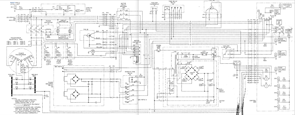
Schematic Notes
A,B,C = 208VAC 3-phase supply
A1,B1,C1 = switched by motor contactor = feed to pump, fan
A2,B2,C2 = after motor breaker = control power = testpoint 1, testpoint 2, testpoint 3
A3,B3,C3 = switched by overvoltage relay = feed to phase sequence relay
A4,B4,C4 = switched by lamp power contactor = feed to power jumper, lamp transformer = testpoint 6 (A4)
1 = ground
6 = C2 switched by phase sequence relay (ok) = feed to time delay relay contact (to #8), control box main switch, control box lights
7 = C2 switched by phase sequence relay (reversed) = feed to control box indicator (PHASE REVERSED)
8 = motor contactor coil = #6 switched by time delay relay = testpoint 4
9 = ignitor = #C2 switched by control panel main (START) = testpoint 7
10 = #C2 switched by overvoltage relay = feed to control box indicator (OVER VOLTAGE)
12 = power on = #6 switched by control panel main (ON, START) = feed to time delay relay coil, coolant flow switch; feed to ARCTIC START switch (coolant flow switch bypass)
13 = #12 switched by coolant flow switch (good flow)
14 = lamp power contactor coil = #13 switched by coolant thermostat (not overtemp) = testpoint 5; switched by ARCTIC START switch (coolant flow switch bypass) to #12
15 = bus negative = feed to voltmeter
16 = bus positive after shunt = feed to voltmeter
17 = bus positive before shunt = feed to ammeter
18 = bus positive after shunt = feed to voltmeter switch (coolant flow switch bypass)
– = rectified bus negative
+ = rectified bus positive
Test Point Indication
1 = phase A after motor circuit breaker (#A2)
2 = phase B after motor circuit breaker (#B2)
3 = phase C after motor circuit breaker (#C2)
4 = time delay relay output/motor contactor coil input (#8)
5 = coolant overtemp switch output (#14)
6 = main power contactor relay output (#A4)
7 = input to starter (#9)
Panel lights = output from overvoltage relay and phase sequence relay (#6)
Component List
CB1: outlet circuit breaker
CB2: motor circuit breaker: 3pole 15A 400Hz
CR1-3: lamp rectifier (cathode to case)
CR4-6: lamp rectifier (anode to case)
K1: Power contactor: 100A 3PST 120V AC 60Hz 400 Hz coil MS24168-A3 Cutler Hammer 6042H289
K2: Overvoltage relay: Leach 9220-8591 4PDT
K3: Phase sequence relay: Hartman AVR869L, 400Hz , SPDT relay actuates with correct 3phase input
K4: Time delay relay: DPDT 120s delay off – Agastat 2122AH3UH, Varo 9992 (115V 400Hz 120s)
K5: Motor contactor: 3PST 120V 400Hz coil
M1: volt meter
M2: amp meter
M3: hour meter
RS1: shunt
S1: coolant thermal switch: SPST NC 235°F
S2: coolant flow switch: SPDT
S3: off, on, start switch DPDT off-on-momentary
S4, S5, S6, S7 illumination switches SPST
S8: test point switch: 8PST rotary
Arctic Start Mod: SPST momentary switch between #12 (control panel main switch) and #14 (testpoint 5)
